
Pipefection
Win64, EnglishGeneral Usage Instructions
For more detailed information on how the program works, please check out the YouTube tutorial videos and the User’s Manual that came with the installation.
YouTube tutorial videos:
https://www.youtube.com/channel/UC5ljZw9VvF63ga_SsQDBryQ/videos
1) Starting to the Pipefection
2) Working Principles
3) Pipe Type Settings
4) General Settings
5) Block Adjustments
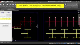
6) Floor Definitions
7) Dimension Label Adjustments
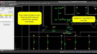
8) Defining Diversity Factors and Load Labels
In summary, the Pipefection works as follows:
The startpoint of the pipeline to be dimensioned is selected from the (B) list and the “Define Network” button is pressed. Pipefection determines the pipe connected to the startpoint, the Discipline to which this pipe belongs is also determined. The pipes and blocks of this Discipline linked together are added to the "Defined Pipeline". After the “Define Network” command is completed, it checks whether the pipeline is properly defined. If not defined correctly, errors are corrected, redefined, and the next step, ‘Size Pipeline’ can be started. Whether the pipes are added to the 'Defined Pipeline' can be determined to check by their colors. The color of the defined pipe entity changes to its calculation color. If there is a discontinuity on the pipeline, the color of the pipeline does not turn into calculation color. In this way, discontinuities can be determined by visual inspection.
When the ‘Size Pipeline’ command is clicked, each pipe component is sized according to the rules of the Discipline to which it belongs.
Drawings can be prepared with Autodesk® AutoCAD® commands. In order to do so the pipeline's drawing components (pipes and equipment blocks) must be defined in the Pipefection Application. These definitions are stored under the Discipline and Discipline Group settings. Any number of Disciplines can be defined under a Discipline group.
Disciplines belonging to the same Discipline Group can be connected to each other with Adapter blocks. For example, there are two Disciplines called 'Fire Wet System' and 'Fire Dry System'. When they are defined under a Discipline Group called a 'Fire Fighting System', they can be connected by an Adapter block called 'Collector' defined in this Discipline Group.
Screenshots


Commands
| Ribbon/Toolbar Icon | Command | Command Description |
|---|---|---|

|
--- |
Using the Settings menu on the Pipefection Tool Palette you can reach the General Settings Menu, Floor Definitions, Pipe Type Settings Form and Block Database Form. |

|
--- |
Using the Toolbox menu on the Pipefection Tool Palette you can reach the Drawing and Import Tool, Edit Dimension Labels Form, Add Load Labels Form and Copy & Mirror with Connections commands. |

|
--- |
Using the “Add New” button on the Pipefection palette, the desired number of start points can be defined in the drawing. The start points defined on the drawing are displayed in the list on the main palette. You can zoom the start points by double-clicking to items on the list. |

|
--- |
Pipefection determines the pipe connected to the start point, the Discipline to which this pipe belongs is also determined. The pipes and blocks of this Discipline linked together are added to the "Defined Pipeline". After the “Define Network” command is completed, it checks whether the pipeline is properly defined. If not defined correctly, errors are corrected, redefined, and the next step, ‘Size Pipeline’ can be started. Whether the pipes are added to the 'Defined Pipeline' can be determined to check by their colors. The color of the defined pipe entity changes to its calculation color. If there is a discontinuity on the pipeline, the color of the pipeline does not turn into calculation color, in this way, discontinuities can be determined by the visual inspection. |
Installation/Uninstallation
The installer that ran when you downloaded this app/plug-in from Autodesk App Store will start installing the app/plug-in. OR, simply double-click the downloaded installer to install the app/plugin.
You may need to restart the Autodesk product to activate the app/plug-in.
To uninstall this plug-in, exit the Autodesk product if you are currently running it, simply rerun the installer, and select the "Uninstall" button. OR, click Control Panel > Programs > Programs and Features (Windows 7/8.1/10) and uninstall as you would any other application from your system.
Additional Information
Known Issues
Contact
Author/Company Information
Support Information
Burock Software:
Version History
| Version Number | Version Description |
|---|---|
|
1.4.0.0 |
Fixed a bug when adding total load. Some message box contents have been changed. |
|
1.3.0.0 |
Support added to Autodesk® AutoCAD® 2020. |
